breeves002
New member
I'm an administrator over on Taurusclub.com, and many of you probably know me! I wanted to share this info with other Ford owners! I'll add more as I learn more. It's about CAN basically. Thanks for reading!
So for the few of you that care about this, I decided to modify a cheap ELM327 clone to read both MS and HS-CAN data. Normally ELM327 can only read HS-CAN data. This writeup will show you how to modify an ELM327 device so it will read MS-CAN.
Thanks to tech advisor behlinla for his help in teaching me some of this info and editing the article!
Info on CAN bus:
Note: Only 2004+ vehicles will have CAN bus (basically if you have digital display in your instrument cluster). OBD-II cars before that used the SAE J1850 PWM protocol, which will still work with FORscan.
Now some of you may be asking: "What in the heck is this guy talking about... MS and HS-CAN???" CAN stands for Controller Area Network, and it's a digital network that connects different modules in your car much like computers would be connected to a network (LAN) in your home or workplace. Accessing the data and self-tests on this network will be useful if you want to troubleshoot problems with something other than the engine (like with the ABS or air bags for example). In the past you used to have to buy very expensive scan tools and software to view this data, but now you can can have this information at your fingertips for as little as $10!
There are two separate CAN buses on most vehicles before 2013, called HS-CAN (High Speed) and MS-CAN (Medium Speed). HS-CAN is used for 'priority' data, like engine parameters (PCM) and critical communication between safety modules like the ABS and RCM. MS-CAN is used more for things inside the car like radio, climate, and lighting control.
In new cars (2013+), nearly every function and control goes over a CAN bus. They have four CAN buses (3x HS and 1x MS) because there is much more data flying around. Things on CAN would be your headlamp switch, drivers door switches, hazard lights, turn signal stalk, dimmer switches, seat adjustments, mirror adjustments, any button on your dash, you name it! I need to scan a 2013+ Ford to actually find out what modules there are!
The HS and MS-CAN buses are bridged together in the instrument panel cluster (IPC) so data can be shared between networks if required. In the 2013+ they bridge together in a separate gateway module.
HS-CAN modules:
-PCM (Powertrain Control Module)
-ABS (Anti-lock Brake System, includes AdvanceTrac and Traction Control)
-RCM (Restraint Control Module, AKA airbags and seatbelts)
-AWD (All Wheel Drive module, if equipped)
-OCSM (Occupent Classification System Module, AKA Passenger Seat Sensors)
-PAM (Parking Aid Module)
-IPC (Instrument Panel Cluster)
-BdyCM (Body Control Module 2013+)
-ACM (Audio Control Module, 2013+)
-FCIM (Front Controls Interface Module, 2013+)
-PSCM (Power Steering Control Module, Hydraulic PS only)
-SECM (Steering Effort Control Module, Electric PS only)
-CCM (Cruise Control Module)
-SCCM (Steering Column Control Module, 2013+)
-APIM (Accessory Protocol Interface Module AKA SYNC)
MS-CAN modules:
-SJB (Smart Junction Box)
-HVAC (Heating, Ventilation & Air Conditioning module)
-ACM (Audio Control Module, pre 2013)
-DSP (Audio Digital Signal Processing Module)
-DSM (Driver Seat Module)
-DDM (Driver Door Module)
-RFA (Remote Function Actuator Module)
-DCSM (Dual Climate Controlled Seat Module)
-SDARS (Satellite Digital Audio Radio Service)
-FCIM (Front Controls Interface Module, pre 2013)
-FDIM (Front Display Interface Module)
-ILCM (Interior Lighting Control Module)
-HCM-2 (High Beam Control Module)
-SOD-R/L (Side Obstacle Detection Control Module AKA BLIS, a module for each side of the vehicle)
-IPC-MS (Instrument Panel Cluster, MS-CAN)
-GPSM (Global Positioning System Module)
-APIM (Accessory Protocol Interface Module AKA SYNC)
Notice how some modules change busses for the 2013MY. That's probably because they have 3xHS-CAN Busses now instead of 1 HS and 1 MS-CAN bus. Other possibility is they run on both busses and meet at a gateway module. Hopefully will confirm one or the other soon.
There may be other modules on other cars or less modules on some cars. Here's a diagram from a 2011 that show all the modules connected to the CAN: http://revbase.com/BBBMotor/Wd/DownloadPdf?id=875110
How to modify your ELM327:
A bunch of us have cheap eBay ELM327 Clones. Stock they only connect to HS-CAN and will not be able to access MS-CAN. The newer STN1170 chips found in some scan tools already have support for MS-CAN (and GM single wire CAN), so you're set if you have one of those!
It's very simple to modify the device to allow use of MS-CAN features. You need a dual position, dual pole (DPDT) switch. Flipping the switch will direct either the HS- or MS-CAN terminal pair in the DLC to the input of the ELM327 chip.

Instructions adapted from here: http://forscan.org/howto.html
Step 1: Crack open the clone or your ELM327 Device. Usually there are 4 screws under the sticker.
Step 2: Unplug the OBD-II connector and un-solder wires connected to pins 6 and 14 (mark them so you know which is which).
Step 3: Solder 2 new wires to pins 6 and 14 (HS-CAN pair) on the OBD-II connector.
Step 4: Solder 2 new wires to pins 3 and 11 (MS-CAN pair) on the OBD-II connector.
Step 5: Solder the wires originally on pins 6 and 14 to the two middle poles on the switch.
Step 6: Solder the new wires on 6 and 14 to one side of the switch (be sure the polarity is correct. Pin 6 will match up with the one originally on pin 6)
Step 7: Solder the new wires on 3 and 11 to the other side of the switch. Be sure to keep pin 3 with the one originally on pin 6 for polarity purposes.
BE SURE NOT TO MIX UP MS-CAN AND HS-CAN AND OBSERVE POLARITY!!! Bad things happen if you do that. I used RED wires for HS-CAN and Black wires for MS-CAN.
A few diagrams of how it works:
Diagrams are showing the dash connector view, reverse for the scan tool view!


Pictures of the process and final product:
My ELM327 motherboard:

Wires soldered onto the OBD-II connector:

Switch installed (oops forgot some heat shrink):

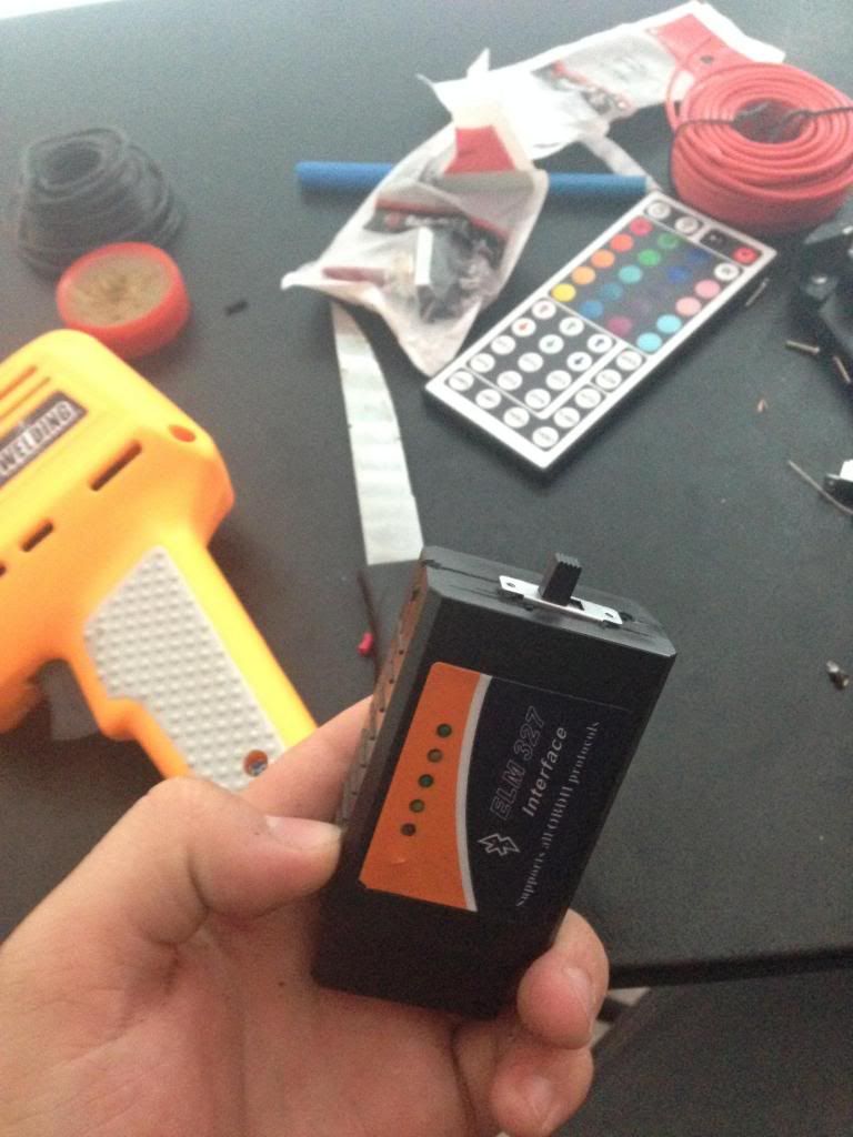
All in the little package waiting to be put back together, also the crappy hole I cut:

Finished product!:
HOW TO ACCESS MS-CAN VIA FORSCAN:
Now when you open FORScan it will ask you if you have an MS/HS CAN switch. SAY YES! You may have to delete your cars profile, close the program, re-open it, then connect again for it to ask you the question. Annoyingly I have to do this almost every time I use the program!

Please feel free to PM me with any questions. I'll be happy to sell anyone one of these modified for $29 including shipping.
FORSCAN.org - Download it today. May be the best free software out there!
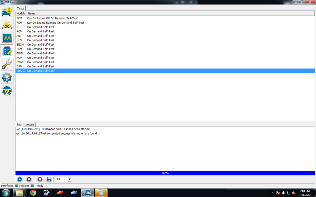
Once you get connected you can do everything you can do on OBDWiz and ScanXL (pretty much), but you can also run self tests over both HS-CAN and MS-CAN. Here are the modules I can see and tests I can run:
So for the few of you that care about this, I decided to modify a cheap ELM327 clone to read both MS and HS-CAN data. Normally ELM327 can only read HS-CAN data. This writeup will show you how to modify an ELM327 device so it will read MS-CAN.
Thanks to tech advisor behlinla for his help in teaching me some of this info and editing the article!
Info on CAN bus:
Note: Only 2004+ vehicles will have CAN bus (basically if you have digital display in your instrument cluster). OBD-II cars before that used the SAE J1850 PWM protocol, which will still work with FORscan.
Now some of you may be asking: "What in the heck is this guy talking about... MS and HS-CAN???" CAN stands for Controller Area Network, and it's a digital network that connects different modules in your car much like computers would be connected to a network (LAN) in your home or workplace. Accessing the data and self-tests on this network will be useful if you want to troubleshoot problems with something other than the engine (like with the ABS or air bags for example). In the past you used to have to buy very expensive scan tools and software to view this data, but now you can can have this information at your fingertips for as little as $10!
There are two separate CAN buses on most vehicles before 2013, called HS-CAN (High Speed) and MS-CAN (Medium Speed). HS-CAN is used for 'priority' data, like engine parameters (PCM) and critical communication between safety modules like the ABS and RCM. MS-CAN is used more for things inside the car like radio, climate, and lighting control.
In new cars (2013+), nearly every function and control goes over a CAN bus. They have four CAN buses (3x HS and 1x MS) because there is much more data flying around. Things on CAN would be your headlamp switch, drivers door switches, hazard lights, turn signal stalk, dimmer switches, seat adjustments, mirror adjustments, any button on your dash, you name it! I need to scan a 2013+ Ford to actually find out what modules there are!
The HS and MS-CAN buses are bridged together in the instrument panel cluster (IPC) so data can be shared between networks if required. In the 2013+ they bridge together in a separate gateway module.
HS-CAN modules:
-PCM (Powertrain Control Module)
-ABS (Anti-lock Brake System, includes AdvanceTrac and Traction Control)
-RCM (Restraint Control Module, AKA airbags and seatbelts)
-AWD (All Wheel Drive module, if equipped)
-OCSM (Occupent Classification System Module, AKA Passenger Seat Sensors)
-PAM (Parking Aid Module)
-IPC (Instrument Panel Cluster)
-BdyCM (Body Control Module 2013+)
-ACM (Audio Control Module, 2013+)
-FCIM (Front Controls Interface Module, 2013+)
-PSCM (Power Steering Control Module, Hydraulic PS only)
-SECM (Steering Effort Control Module, Electric PS only)
-CCM (Cruise Control Module)
-SCCM (Steering Column Control Module, 2013+)
-APIM (Accessory Protocol Interface Module AKA SYNC)
MS-CAN modules:
-SJB (Smart Junction Box)
-HVAC (Heating, Ventilation & Air Conditioning module)
-ACM (Audio Control Module, pre 2013)
-DSP (Audio Digital Signal Processing Module)
-DSM (Driver Seat Module)
-DDM (Driver Door Module)
-RFA (Remote Function Actuator Module)
-DCSM (Dual Climate Controlled Seat Module)
-SDARS (Satellite Digital Audio Radio Service)
-FCIM (Front Controls Interface Module, pre 2013)
-FDIM (Front Display Interface Module)
-ILCM (Interior Lighting Control Module)
-HCM-2 (High Beam Control Module)
-SOD-R/L (Side Obstacle Detection Control Module AKA BLIS, a module for each side of the vehicle)
-IPC-MS (Instrument Panel Cluster, MS-CAN)
-GPSM (Global Positioning System Module)
-APIM (Accessory Protocol Interface Module AKA SYNC)
Notice how some modules change busses for the 2013MY. That's probably because they have 3xHS-CAN Busses now instead of 1 HS and 1 MS-CAN bus. Other possibility is they run on both busses and meet at a gateway module. Hopefully will confirm one or the other soon.
There may be other modules on other cars or less modules on some cars. Here's a diagram from a 2011 that show all the modules connected to the CAN: http://revbase.com/BBBMotor/Wd/DownloadPdf?id=875110
How to modify your ELM327:
A bunch of us have cheap eBay ELM327 Clones. Stock they only connect to HS-CAN and will not be able to access MS-CAN. The newer STN1170 chips found in some scan tools already have support for MS-CAN (and GM single wire CAN), so you're set if you have one of those!
It's very simple to modify the device to allow use of MS-CAN features. You need a dual position, dual pole (DPDT) switch. Flipping the switch will direct either the HS- or MS-CAN terminal pair in the DLC to the input of the ELM327 chip.
Instructions adapted from here: http://forscan.org/howto.html
Step 1: Crack open the clone or your ELM327 Device. Usually there are 4 screws under the sticker.
Step 2: Unplug the OBD-II connector and un-solder wires connected to pins 6 and 14 (mark them so you know which is which).
Step 3: Solder 2 new wires to pins 6 and 14 (HS-CAN pair) on the OBD-II connector.
Step 4: Solder 2 new wires to pins 3 and 11 (MS-CAN pair) on the OBD-II connector.
Step 5: Solder the wires originally on pins 6 and 14 to the two middle poles on the switch.
Step 6: Solder the new wires on 6 and 14 to one side of the switch (be sure the polarity is correct. Pin 6 will match up with the one originally on pin 6)
Step 7: Solder the new wires on 3 and 11 to the other side of the switch. Be sure to keep pin 3 with the one originally on pin 6 for polarity purposes.
BE SURE NOT TO MIX UP MS-CAN AND HS-CAN AND OBSERVE POLARITY!!! Bad things happen if you do that. I used RED wires for HS-CAN and Black wires for MS-CAN.
A few diagrams of how it works:
Diagrams are showing the dash connector view, reverse for the scan tool view!
Pictures of the process and final product:
My ELM327 motherboard:

Wires soldered onto the OBD-II connector:

Switch installed (oops forgot some heat shrink):

All in the little package waiting to be put back together, also the crappy hole I cut:

Finished product!:
HOW TO ACCESS MS-CAN VIA FORSCAN:
Now when you open FORScan it will ask you if you have an MS/HS CAN switch. SAY YES! You may have to delete your cars profile, close the program, re-open it, then connect again for it to ask you the question. Annoyingly I have to do this almost every time I use the program!
Please feel free to PM me with any questions. I'll be happy to sell anyone one of these modified for $29 including shipping.
FORSCAN.org - Download it today. May be the best free software out there!
Once you get connected you can do everything you can do on OBDWiz and ScanXL (pretty much), but you can also run self tests over both HS-CAN and MS-CAN. Here are the modules I can see and tests I can run:
")